Micro-processor technology with diverse redundant processing logic
Administration of up to 144 detector zones for manual call points, automatic fire detectors with or without alarm verification, technical messages and fault detectors with or without self-resetting property
Administration of 10 transmitting devices, 99 alarming devices, 128 actuations and 199 sectors
Easy control panel operation thanks to freely parameterisable sectors
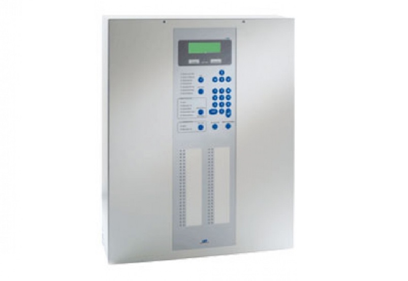
INFO field with a 4 line by 20 character backlit text display providing information about all current events in English
Info button for additional information on the current events
Event memory with quick-search filter displays the latest 500 events in chronological order
Display of activation, fault, disablement, alarm delay, call fire brigade and confirmation of the transmitting device to the fire brigade
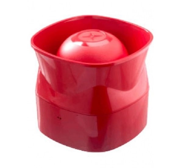
Monitored output for the connection of external signalling devices with display of activation, fault or disablement
Dry contact outputs for summary alarm and summary fault
16 open-collector outputs which can be freely parameterised as transmitting devices, alarming devices, actuations or other output functions
„and/or“-combinations for the activation of actuations, transmitting devices or alarming devices, depending on messages from detector zones or single detectors, respectively
Collective reset of all current alarms via “Panel reset” button
Hierarchized authorisation levels for operation and parameterisation, secured via numeric codes
Alarm delay with dead-man’s handle controlled by internal timer which can be set separately for each day of the week
Start and end date of Daylight Saving Time according to EU directive or freely parameterisable One-man test condition
Non-resettable electronic alarm counter
Two integrated serial interfaces
Integrated INFO bus for the connection of fire brigade control units and intelligent remote indication units
Connection of a serial protocol printer via an optional data interface
Control panel recognises all control panel components and loop elements by means of auto-setup during first commissioning
Connection of detectors via unshielded 2-wire cabling
Stand-by batteries 2 × 12V/max. 22Ah can be installed in the control panel’s housing
The parameters of the control panel can be set up and transmitted to the control panel quickly and reliably by means of a PC and the Windows Parameter Setup Software PARSOFT-1. Additionally, the parameter setup can also be realised without any further tools using the keypad of the integrated display and operating field of the control panel or by means of a commercially available PC keyboard

